The regulating wheel in through-feed centerless grinding may be one of the most misunderstood components in subtractive manufacturing as its function is not obvious at first glance. When I first saw one, I could not wrap my head around how that narrow band of contact between the regulating wheel and the workpiece could possibly control the part well enough to keep it from being thrown by the grinding wheel. As you may know, that can and sometimes does happen. It’s a machine crash heard across the shop and will have you panicking to smash the E-Stop, visiting the men’s room to inspect your underwear, and then walking outside for a smoke all the while your hands are trembling. This endeavor you are about to undertake and the need for caution reminded me of the opening of David L. Goodstein’s textbook States of Matter, where he writes:
“Ludwig Boltzmann, who spent much of his life studying statistical mechanics, died in 1906 by his own hand. Paul Ehrenfest, carrying on the work, died similarly in 1933. Now it is your turn to study statistical mechanics. Perhaps it will be wise to approach the subject cautiously.”
It is now your turn to enter the dark world of centerless grinding. Caution is indeed required here. However, once you begin to understand how the regulating wheel works, it is difficult to stop thinking about its shape and how that shape can provide enough grip to resist the immense rotational forces imparted on the workpiece by the grinding wheel. Compared to more familiar types of machining, the process can seem anything but straightforward and predictable. However, once you understand the geometry of the regulating wheel, the centerless machine begins to make sense—and you will be in the company of very few people who truly grasp the concept.
The important point here is that the regulating wheel is not merely a cylinder, and the contact area is not a thin straight line. The contact area with the workpiece is more of a slight S curve as it runs along the cylindrical face of the regulating wheel, above center at the in-feed side and below center at the out-feed side of the wheel, this shape cradles and supports the work piece with opposing pressure from the work rest. To achieve this contact pattern the regulating wheel is dressed into more of an hour-glass shape.
The shape of a properly dressed regulating wheel for through-feed centerless grinding is more specifically a tilted single-sheet hyperboloid: in simpler terms, a symmetrical sideways hourglass tipped downward toward the workpiece exit. This shape is created as the dressing diamond travels horizontally along an axis parallel to the work rest and grinding wheel axes while the regulating wheel itself is tilted downward toward the workpiece exit anywhere from 1 to 5 degrees. The dressing diamond should be set as close as practical to the height of the contact line between the regulating wheel and the workpiece at the center of the wheel width. If you change workpiece diameters you need to redress the wheel with the diamond at the new contact height to achieve optimal control and through feed motion. The downward tilt of the regulating wheel is also what creates the feeding action. More tilt creates faster through feed.
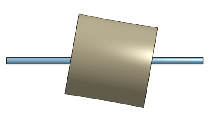
In this picture you can see the hour-glass shape and the exaggerated tilt. Here the shaft would be feeding left to right.
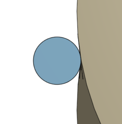
Here’s another view straight at the work piece as it is feed away from you.
The first parameter you should consider when selecting a regulating wheel is bond. Bond is the structural component of the regulating wheel that gives shape and holds the abrasive media.
- Rubber Bonded
- Most common, most versatile, most available range of abrasives
- Excellent grip and vibration dampening
- Best choice for steel and stainless-steel work piece materials in through feed applications
- Resin / Epoxy Bonded
- Much harder and more rigid when compared to rubber
- Better suited for heavy stock removal and more irregular shapes of work pieces
- Best suited for stepped or irregular shaped work pieces and in-feed grinding
- Vitrified Bond
- Extremely rigid and unforgiving
- Not suitable for grinding common ferrous and non-ferrous materials
- Best suited for ceramic and glass work piece materials
My recommendation is to purchase a regulating wheel from a manufacturer that you are comfortable with as long as they use the calendaring process in the case of rubber bonded and match the abrasive gain similarly to how you would in a grinding wheel, lower number is larger grains for better grip but rough surface finish. Higher number is smaller grains with less grip but with a finer surface finish, the finer wheels are also less likely to scratch a finely finished part.
Now that you have selected a regulating wheel and you have it mounted it is time to dress the regulating wheel. We will discuss the tilt angle in a later article, for now let’s focus on the dressing diamond “setover” or distance from the regulating wheel center line. See below.
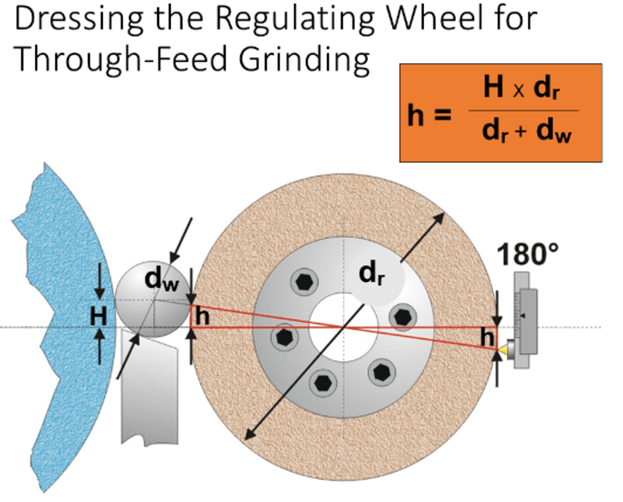
You can use the formula above to determine (h) dresser setover, however I prefer to calculate more accurately using the gamma angle as shown below. It is helpful to create a CAD drawing as shown and it can also be used in the future as the wheels wear, and you change work piece diameters. Below are 2 likely strategies 6.5 degree and 6.67 degree gamma angles. I have found that longer parts grind better at 6.5 degrees and shorter parts grind better at 6.67 degrees, this is not always true, however I tend to start with 6.67 degrees and see how that performs first before making any changes.
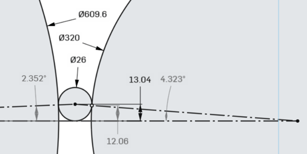
Gamma angle) 6.67 degrees (2.352 + 4.323)
H) 13.04mm work piece center height achieved by position of work blade
h) 12.06mm single point dressing height (tangent point)
dw) 26mm work piece diameter
dg) 609.6mm grinding wheel diameter
dr) 320mm regulating wheel diameter
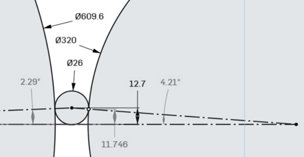
Gamma angle) 6.50 degrees (2.352 + 4.323)
H) 12.7mm work piece center height achieved by position of work blade
h) 11.746mm single point dressing height (tangent point)
dw) 26mm work piece diameter
dg) 609.6mm grinding wheel diameter
dr) 320mm regulating wheel diameter
Now it is your turn to study and practice centerless grinding. I will write more of these articles if you find them useful. Please email me if you find this helpful or totally disagree with something I have written. Your feedback either way is greatly appreciated.
centerless@centerlesshelp.com, thank you for reading, and Godspeed.
 Centerlesshelp.com
Leave a comment